File:0353-97-231.pdf
← Older revision
Revision as of 06:22, 14 October 2014
Line 1:
Line 1:
- +== Licensing ==
+{{CERN OHLv1.1 }}
Andrey.filippov
File:0353-97-231.pdf
uploaded "[[File:0353-97-231.pdf]]"
Andrey.filippovFile:0353-97-201.stp.tar.gz
uploaded "[[File:0353-97-201.stp.tar.gz]]"
Andrey.filippovElphel camera parts 0353-01
0353-01-555 - Eyesis4Pi SATA-eSATA power 1-to-2 cable:
← Older revision Revision as of 17:07, 8 October 2014 Line 158: Line 158: ---- ---- -=== 0353-01-555 - Eyesis4Pi SATA-eSATA power 1-to-2 cable ===+=== 0353-01-556 - Eyesis4Pi mSATA-SATA cable with power === {| border="0" cellpadding="2" {| border="0" cellpadding="2" |- |- -| [[Image:0353-01-555.png|thumb|[[Media:0353-01-555.pdf|2d (pdf)]]]] +| [[Image:0353-01-556.png|thumb|[[Media:0353-01-556.pdf|2d (pdf)]]]] |- |- |} |} -1 x CONN RECEPT 2POS 3MM SINGLE ROW (Molex: 0436450200) dk p/n WM18457-ND+1 x CONN SOCKET HOUSING 2POS 1.25MM dk p/n H2179-ND -2 x CONN SOCKET 20-24AWG GOLD (Molex: 0462350001) dk p/n WM7082CT-ND+2 x CONN CONTACT 26-30AWG CRIMP GOLD dk p/n H9991CT-ND -1 x CABLE ASSY 5.5X2.1MM M/F 14' (~10AWG) dk p/n 839-1173-ND+ OlgaFile:0353-01-556.pdf
uploaded "[[File:0353-01-556.pdf]]" Eyesis4Pi mSATA-SATA cable with power
OlgaElphel camera parts 0353-01
0353-01-553 - Eyesis4Pi 10369 power cable 1-to-4 (for head cameras):
← Older revision Revision as of 17:02, 8 October 2014 (One intermediate revision not shown)Line 127: Line 127: {| border="0" cellpadding="2" {| border="0" cellpadding="2" |- |- -| [[Image:0353-01-552.png|thumb|[[Media:0353-01-552.pdf|2d (pdf)]]]] +| [[Image:0353-01-553.png|thumb|[[Media:0353-01-553.pdf|2d (pdf)]]]] |- |- |} |} Line 133: Line 133: 10 x CONN SOCKET 20-24AWG GOLD (Molex: 0462350001) dk p/n WM7082CT-ND 10 x CONN SOCKET 20-24AWG GOLD (Molex: 0462350001) dk p/n WM7082CT-ND ---- ---- -=== 0353-01-555 - Eyesis4Pi SATA-eSATA power 1-to-2 cable ===+ +=== 0353-01-554 - Eyesis4Pi SATA-eSATA power 1-to-2 cable === {| border="0" cellpadding="2" {| border="0" cellpadding="2" |- |- -| [[Image:0353-01-552.png|thumb|[[Media:0353-01-552.pdf|2d (pdf)]]]] +| [[Image:0353-01-554.png|thumb|[[Media:0353-01-554.pdf|2d (pdf)]]]] |- |- |} |} Line 144: Line 145: 4 x CONN TERM 26-28AWG CRIMP GOLD dk p/n H1577CT-ND 4 x CONN TERM 26-28AWG CRIMP GOLD dk p/n H1577CT-ND ---- ---- + +=== 0353-01-555 - Eyesis4Pi SATA-eSATA power 1-to-2 cable === +{| border="0" cellpadding="2" +|- +| [[Image:0353-01-555.png|thumb|[[Media:0353-01-555.pdf|2d (pdf)]]]] +|- +|} +1 x CONN RECEPT 2POS 3MM SINGLE ROW (Molex: 0436450200) dk p/n WM18457-ND +2 x CONN SOCKET 20-24AWG GOLD (Molex: 0462350001) dk p/n WM7082CT-ND +1 x CABLE ASSY 5.5X2.1MM M/F 14' (~10AWG) dk p/n 839-1173-ND + +---- + +=== 0353-01-555 - Eyesis4Pi SATA-eSATA power 1-to-2 cable === +{| border="0" cellpadding="2" +|- +| [[Image:0353-01-555.png|thumb|[[Media:0353-01-555.pdf|2d (pdf)]]]] +|- +|} +1 x CONN RECEPT 2POS 3MM SINGLE ROW (Molex: 0436450200) dk p/n WM18457-ND +2 x CONN SOCKET 20-24AWG GOLD (Molex: 0462350001) dk p/n WM7082CT-ND +1 x CABLE ASSY 5.5X2.1MM M/F 14' (~10AWG) dk p/n 839-1173-ND OlgaFile:0353-01-555.pdf
uploaded "[[File:0353-01-555.pdf]]" Eyesis4Pi SATA-eSATA power 1-to-2 cable
OlgaElphel camera parts 0353-01
0353-01-553 - Eyesis4Pi 10369 power cable 1-to-4 (for head cameras):
← Older revision Revision as of 16:40, 8 October 2014 (2 intermediate revisions not shown)Line 114: Line 114: 1 x CONN RECEPT 4POS 3MM SINGLE ROW (Molex: 0436450400) dk p/m WM1847-ND 1 x CONN RECEPT 4POS 3MM SINGLE ROW (Molex: 0436450400) dk p/m WM1847-ND 4 x CONN SOCKET 20-24AWG GOLD (Molex: 0462350001) dk p/m WM7082CT-ND 4 x CONN SOCKET 20-24AWG GOLD (Molex: 0462350001) dk p/m WM7082CT-ND +---- +=== 0353-01-552 - Eyesis4Pi 10369 power cable for stereo pair camera & switch === +{| border="0" cellpadding="2" +|- +| [[Image:0353-01-552.png|thumb|[[Media:0353-01-552.pdf|2d (pdf)]]]] +|- +|} +2 x CONN RECEPT 4POS 3MM SINGLE ROW (Molex: 0436450400) dk p/m WM1847-ND +4 x CONN SOCKET 20-24AWG GOLD (Molex: 0462350001) dk p/m WM7082CT-ND +---- +=== 0353-01-553 - Eyesis4Pi 10369 power cable 1-to-4 (for head cameras) === +{| border="0" cellpadding="2" +|- +| [[Image:0353-01-552.png|thumb|[[Media:0353-01-552.pdf|2d (pdf)]]]] +|- +|} +5 x CONN RECEPT 4POS 3MM SINGLE ROW (Molex: 0436450400) dk p/n WM1847-ND +10 x CONN SOCKET 20-24AWG GOLD (Molex: 0462350001) dk p/n WM7082CT-ND +---- +=== 0353-01-555 - Eyesis4Pi SATA-eSATA power 1-to-2 cable === +{| border="0" cellpadding="2" +|- +| [[Image:0353-01-552.png|thumb|[[Media:0353-01-552.pdf|2d (pdf)]]]] +|- +|} +1 x CONN RECEPT 4POS 3MM SINGLE ROW (Molex: 0436450400) dk p/n WM1847-ND +2 x CONN SOCKET 20-24AWG GOLD (Molex: 0462350001) dk p/n WM7082CT-ND +2 x CONN SOCKET 2POS 1.25MM CRIMP dk p/n H1563-ND +4 x CONN TERM 26-28AWG CRIMP GOLD dk p/n H1577CT-ND +---- OlgaElphel camera parts 0353-01
0353-01-551 - Eyesis4Pi power cable for SSD MUX:
← Older revision Revision as of 20:13, 7 October 2014 Line 114: Line 114: 1 x CONN RECEPT 4POS 3MM SINGLE ROW (Molex: 0436450400) dk p/m WM1847-ND 1 x CONN RECEPT 4POS 3MM SINGLE ROW (Molex: 0436450400) dk p/m WM1847-ND 4 x CONN SOCKET 20-24AWG GOLD (Molex: 0462350001) dk p/m WM7082CT-ND 4 x CONN SOCKET 20-24AWG GOLD (Molex: 0462350001) dk p/m WM7082CT-ND +---- +=== 0353-01-552 - Eyesis4Pi 10369 power cable for stereo pair camera & switch === +{| border="0" cellpadding="2" +|- +| [[Image:0353-01-552.png|thumb|[[Media:0353-01-552.pdf|2d (pdf)]]]] +|- +|} +2 x CONN RECEPT 4POS 3MM SINGLE ROW (Molex: 0436450400) dk p/m WM1847-ND +4 x CONN SOCKET 20-24AWG GOLD (Molex: 0462350001) dk p/m WM7082CT-ND +---- OlgaFile:0353-01-552.pdf
uploaded "[[File:0353-01-552.pdf]]" Eyesis4Pi 10369 power cable for stereo pair camera & switch
OlgaElphel camera parts 0353-01
0353-01-51 - FPC flexible printed circuit straight for panoramic head:
← Older revision Revision as of 20:05, 7 October 2014 Line 103: Line 103: === 0353-01-50 - FPC flexible printed circuit 90 degree for panoramic head === === 0353-01-50 - FPC flexible printed circuit 90 degree for panoramic head === === 0353-01-51 - FPC flexible printed circuit straight for panoramic head === === 0353-01-51 - FPC flexible printed circuit straight for panoramic head === +---- === 0353-01-551 - Eyesis4Pi power cable for SSD MUX === === 0353-01-551 - Eyesis4Pi power cable for SSD MUX === OlgaFile:0353-01-551.png
uploaded a new version of "[[File:0353-01-551.png]]" SATA MUX cable for Eyesis4Pi26-SSD
Olga
Elphel camera parts 0353-01
0353-01-551 - Eyesis4Pi power cable for SSD MUX:
← Older revision Revision as of 20:02, 7 October 2014 (One intermediate revision not shown)Line 107: Line 107: {| border="0" cellpadding="2" {| border="0" cellpadding="2" |- |- -| [[Image:0353-01-42.jpeg|thumb]] +| [[Image:0353-01-551.png|thumb|[[Media:0353-01-551.pdf|2d (pdf)]]]] |- |- |} |} OlgaFile:0353-01-551.pdf
uploaded "[[File:0353-01-551.pdf]]" SATA MUX cable for Eyesis4Pi26-SSD
OlgaElphel camera parts 0353-01
0353-01-551 - Eyesis4Pi power cable for SSD MUX:
← Older revision Revision as of 19:40, 7 October 2014 (2 intermediate revisions not shown)Line 103: Line 103: === 0353-01-50 - FPC flexible printed circuit 90 degree for panoramic head === === 0353-01-50 - FPC flexible printed circuit 90 degree for panoramic head === === 0353-01-51 - FPC flexible printed circuit straight for panoramic head === === 0353-01-51 - FPC flexible printed circuit straight for panoramic head === + +=== 0353-01-551 - Eyesis4Pi power cable for SSD MUX === +{| border="0" cellpadding="2" +|- +| [[Image:0353-01-42.jpeg|thumb]] +|- +|} +1 x CONN RECEPT 2POS 3MM SINGLE ROW (Molex: 0436450200) dk p/m WM1845-ND +1 x CONN RECEPT 4POS 3MM SINGLE ROW (Molex: 0436450400) dk p/m WM1847-ND +4 x CONN SOCKET 20-24AWG GOLD (Molex: 0462350001) dk p/m WM7082CT-ND OlgaRelease notes
← Older revision
Revision as of 23:14, 26 September 2014
Line 9:
Line 9:
The most recent (and definitely "unstable") software is available on CVS at Sourceforge. The software available only from the CVS has 4 dot-separated numbers, the thirst three matching the last version released as a tarball distribution on SourceForge. The most recent (and definitely "unstable") software is available on CVS at Sourceforge. The software available only from the CVS has 4 dot-separated numbers, the thirst three matching the last version released as a tarball distribution on SourceForge.
+
+== How-To Release (for developers)==
+
+===Update the Release Number===
+* Build
+* Change the DEV_BOARD_VERSION in ''elphel353/configure-files/elphel_release''
+* Rebuild
+* Rename target.list.new > target.list
+* Rebuild
+* Commit the changes
+
+===Add new files===
+* Build
+* Add new files to the list in ''elphel353/src.list''
+* Rebuild
+* Add files to CVS and commit the changes
+
+===Add external package===
+* Build
+* Edit ''configure-files/post'' providing package name and download address
+* ...Patching...
+* Rebuild
+* Rename target.list.new > target.list
+
+* Rebuild
+* Commit the changes
== Next Upcoming Release == == Next Upcoming Release ==
Oleg
Elphel camera parts 0353-19
0353-19-45 - SFE Cradle, Top:
← Older revision Revision as of 01:25, 12 September 2014 Line 190: Line 190: ---- ---- + +=== 0353-19-45B - SFE Cradle, Top Rev "B" === +{{Cad4|0353-19-45B}} + +---- + === 0353-19-46 - SFE Cradle, handle === === 0353-19-46 - SFE Cradle, handle === {{Cad4|0353-19-46}} {{Cad4|0353-19-46}} Andrey.filippovFile:0353-19-45B.stp.tar.gz
uploaded "[[File:0353-19-45B.stp.tar.gz]]"
Andrey.filippovMore lenses tested: Evetar N123B05425W vs. Sunex DSL945D
We just tested two samples of Evetar N123B05425W lens that is very similar to Sunex DSL945D described in the previous post.
Lens Specifications
Sunex DSL945D
Evetar N123B05425W
Focal length
5.5mm
5.4mm
F#
1/2.5
1/2.5
IR cutoff filter
yes
yes
Lens mount
M12
M12
image format
1/2.3
1/2.3
Recommended sensor resolution
10Mpix
10MPix
Both lenses are specified to work with 10 megapixel sensors, so it is possible to compare “apples to apples”. This performance compaison is based only on our testing procedure and does not involve any additional data from the lens manufacturers, the lens samples were randomly selected from the purchased devices. Different applications require different features (or combination of features) of the lens, and both lenses have their advantages with respect to the other.
Sunex lens has very low longitudinal chromatic aberration (~5μm) as indicated on “Astigmatism” (bottom left) graphs, it is well corrected so both red and blue curves are on the same side of the green one. Evetar lens have very small difference between red and green, but blue is more than 15 μm off. My guess is that the factory tried to make the lens that can work in “day/night” applications and optimized design for visible and infrared spectrum simultaneously. Sacrificing infrared (it anyway has no value in high resolution visible light applications) at the design stage could improve performance of this already very good product.
Petzval field curvature of the DSL945D is slightly better than that of the N123B05425W, astigmatism (difference between the sagittal and the tangential focal shift for the same color) is almost the same with maximum of 18 μm at ~2 mm from the image center.
Center resolution (mtf50% is shown) of the DSL945D is higher for each color, but only in the center. It drops for peripheral areas much quicker than the resolution of the N123B05425W does. Evetar lens has only sagittal (radial) resolution for blue component dropping below 100 lp/mm according to our measurements, and that gives this lens higher full-field weighted resolution values (top left plot on each figure).
Lens testing dataThe graphs below and the testing procedure are described in the previous post. Solid lines correspond to the tangential and dashed – to the sagittal components for the radial aberration model, point marks account for the measured parameter variations in the different parts of the lenses at the same distance from the center.
Sunex DSL945D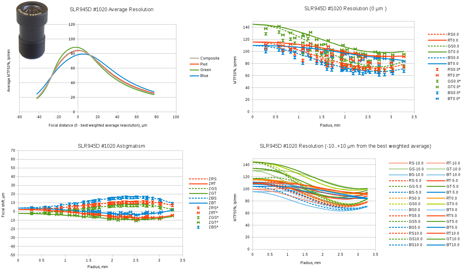
Fig.1 Sunex SLR945D sample #1020 test results. Spreadsheet link.
Evetar N123B05425W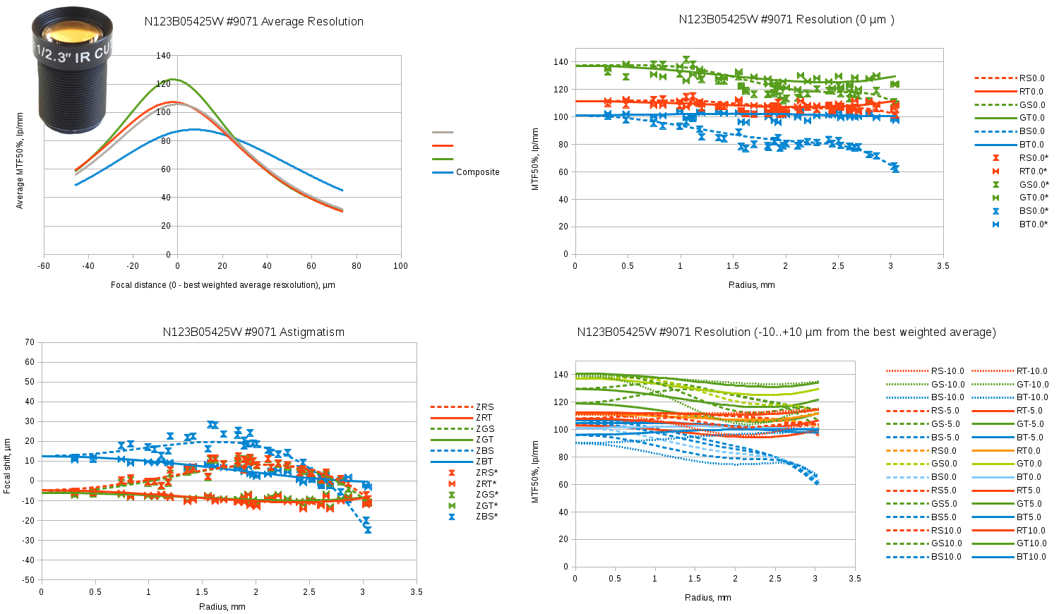
Fig.2 Evetar N123B05425W sample #9071 test results. Spreadsheet link.
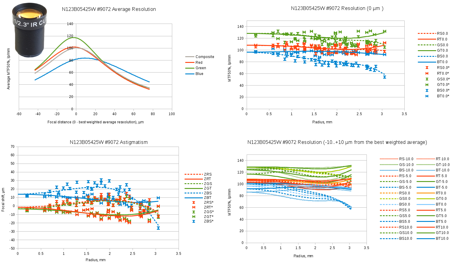
Fig.3 Evetar N123B05425W sample #9072 test results. Spreadsheet link.
File:0353-19-481.pdf
uploaded a new version of "[[File:0353-19-481.pdf]]"
Andrey.filippov