Poky 2.0 manual
Setup:
← Older revision Revision as of 07:03, 8 March 2016 Line 50: Line 50: '''#Part 2 : init environment and auto-fill Yocto's conf-files''' '''#Part 2 : init environment and auto-fill Yocto's conf-files''' + CONF_NOTES="meta/conf/conf-notes.txt" + + if [ -f $CONF_NOTES ]; then + rm $CONF_NOTES + fi + + echo "Common \"elphel393\" targets are:" >> $CONF_NOTES + echo " u-boot" >> $CONF_NOTES + echo " device-tree" >> $CONF_NOTES + echo " linux-xlnx" >> $CONF_NOTES + echo " core-image-elphel393" >> $CONF_NOTES CURRENT_PATH=$(dirname $(readlink -f "$0")) CURRENT_PATH=$(dirname $(readlink -f "$0")) OlegMicrozed issues
List:
← Older revision Revision as of 22:35, 23 February 2016 (4 intermediate revisions not shown)Line 1: Line 1: ==List== ==List== -* <b style='color:green'>[SOLVED]</b> UART+===<b style='color:green'>[CLEARED]</b> UART=== <font size='2'> <font size='2'> <b>Description:</b> <b>Description:</b> Line 31: Line 31: </font> </font> -* SSH terminal+===<b style='color:green'>[CLEARED]</b> SSH terminal=== <font size='2'> <font size='2'> <b>Description:</b> <b>Description:</b> Freezes, lags but remembers all typed symbols Freezes, lags but remembers all typed symbols <b>Possible reason:</b> <b>Possible reason:</b> - Bad network cable? Network problem?+ Devices with identical MACs in LAN </font> </font> -* RTC+===RTC=== <font size='2'> <font size='2'> - Too many messages when rtc is missing <b>Description:</b> <b>Description:</b> + Not an issue 3x"hwclock: can't open '/dev/misc/rtc': No such file or directory" in boot log 3x"hwclock: can't open '/dev/misc/rtc': No such file or directory" in boot log <b>Possible reason:</b> <b>Possible reason:</b> - driver+ a. Microzed doesn't have a real-time clock (rtc) + b. Reported by /etc/init.d/hwclock.sh - not the driver </font> </font> -* U-boot Falcon mode (boot from SPL directly to OS avoiding full u-boot)+===U-boot Falcon mode (boot from SPL directly to OS avoiding full u-boot)=== <font size='2'> <font size='2'> <b>Description:</b> <b>Description:</b> Line 53: Line 54: <b>Possible reason:</b> <b>Possible reason:</b> -* U-boot spl reads u-boot-dtb.img 2 times+===U-boot spl reads u-boot-dtb.img 2 times=== <font size='2'> <font size='2'> <b>Description:</b> <b>Description:</b> Line 92: Line 93: </font> </font> - -* hwclock multiple error messages -<font size='2'> - <b>Description:</b> - Not an issue - "hwclock: can't open '/dev/misc/rtc': No such file or directory" repeated 3 times - <b>Possible reason:</b> - a. Microzed doesn't have a real-time clock (rtc) - b. Reported by /etc/init.d/hwclock.sh - not the driver ==Useful pages== ==Useful pages== OlegMicrozed issues
← Older revision
Revision as of 01:19, 20 February 2016
(One intermediate revision not shown)Line 1:
Line 1:
==List== ==List==
-* <b style='color:green'>[SOLVED]</b> UART+===<b style='color:green'>[SOLVED]</b> UART===
<font size='2'> <font size='2'>
<b>Description:</b> <b>Description:</b>
Line 31:
Line 31:
</font> </font>
-* SSH terminal+===SSH terminal===
<font size='2'> <font size='2'>
<b>Description:</b> <b>Description:</b>
Line 38:
Line 38:
Bad network cable? Network problem? Bad network cable? Network problem?
</font> </font>
-* RTC+===RTC===
<font size='2'> <font size='2'>
- Too many messages when rtc is missing+ Not an issue
+ "hwclock: can't open '/dev/misc/rtc': No such file or directory" repeated 3 times
<b>Description:</b> <b>Description:</b>
3x"hwclock: can't open '/dev/misc/rtc': No such file or directory" in boot log 3x"hwclock: can't open '/dev/misc/rtc': No such file or directory" in boot log
<b>Possible reason:</b> <b>Possible reason:</b>
- driver+ a. Microzed doesn't have a real-time clock (rtc)
+ b. Reported by /etc/init.d/hwclock.sh - not the driver
</font> </font>
-* U-boot Falcon mode (boot from SPL directly to OS avoiding full u-boot)+===U-boot Falcon mode (boot from SPL directly to OS avoiding full u-boot)===
<font size='2'> <font size='2'>
<b>Description:</b> <b>Description:</b>
Line 53:
Line 55:
<b>Possible reason:</b> <b>Possible reason:</b>
-* U-boot spl reads u-boot-dtb.img 2 times+===U-boot spl reads u-boot-dtb.img 2 times===
<font size='2'> <font size='2'>
<b>Description:</b> <b>Description:</b>
Line 92:
Line 94:
</font> </font>
-
-* hwclock multiple error messages
-<font size='2'>
- <b>Description:</b>
- Not an issue
- "hwclock: can't open '/dev/misc/rtc': No such file or directory" repeated 3 times
- <b>Possible reason:</b>
- a. Microzed doesn't have a real-time clock (rtc)
- b. Reported by /etc/init.d/hwclock.sh - not the driver
==Useful pages== ==Useful pages==
Oleg
Poky 2.0 manual
Setup:
← Older revision Revision as of 01:13, 20 February 2016 Line 41: Line 41: git clone -b master https://github.com/Elphel/meta-elphel393.git meta-elphel393 git clone -b master https://github.com/Elphel/meta-elphel393.git meta-elphel393 - cd meta-elphel393; git checkout e8c6e139848a21b1bf0c05b306108e390bc44e24; cd ..+ cd meta-elphel393; git checkout c5237f99d94217bff8c9180bed93ee673c9590a1; cd .. git clone -b master https://github.com/Xilinx/meta-xilinx.git meta-xilinx git clone -b master https://github.com/Xilinx/meta-xilinx.git meta-xilinx OlegMicrozed issues
New page
==List==* <b style='color:green'>[SOLVED]</b> UART
<font size='2'>
<b>Description:</b>
UART register contents: timeout=0 rxfifo_level=56, should be timeout=10 rxfifo_level=56
minicom prints 56 symbols at a time when rxfifo reaches its level.
remembers all typed symbols
sometimes the timeout register is set correctly
<b>Possible reason:</b>
In driver .startup and .termios conflict? Racing Resets or reset takes time?
<b>Solution:</b>
Added a delay after reset - some other functions in the driver also have it - some not. Luck?
<b>Patch:</b>
<i>diff --git a/drivers/tty/serial/xilinx_uartps.c b/drivers/tty/serial/xilinx_uartps.c
index f214c7f..164e32d 100644
--- a/drivers/tty/serial/xilinx_uartps.c
+++ b/drivers/tty/serial/xilinx_uartps.c
@@ -704,6 +704,9 @@ static void cdns_uart_set_termios(struct uart_port *port,
ctrl_reg |= CDNS_UART_CR_TXRST | CDNS_UART_CR_RXRST;
cdns_uart_writel(ctrl_reg, CDNS_UART_CR_OFFSET);
+ while (cdns_uart_readl(CDNS_UART_CR_OFFSET) &
+ (CDNS_UART_CR_TXRST | CDNS_UART_CR_RXRST))
+ cpu_relax();
/*
* Clear the RX disable and TX disable bits and then set the TX enable
* bit and RX enable bit to enable the transmitter and receiver.</i>
<b>Links:</b>
* https://forums.xilinx.com/t5/Zynq-All-Programmable-SoC/Zynq-Uart-timeout-problem/td-p/432016
* http://www.makelinux.net/ldd3/chp-7-sect-3
</font>
* SSH terminal
<font size='2'>
<b>Description:</b>
Freezes, lags but remembers all typed symbols
<b>Possible reason:</b>
Bad network cable? Network problem?
</font>
* RTC
<font size='2'>
Too many messages when rtc is missing
<b>Description:</b>
3x"hwclock: can't open '/dev/misc/rtc': No such file or directory" in boot log
<b>Possible reason:</b>
driver
</font>
* U-boot Falcon mode (boot from SPL directly to OS avoiding full u-boot)
<font size='2'>
<b>Description:</b>
Try
<b>Possible reason:</b>
* U-boot spl reads u-boot-dtb.img 2 times
<font size='2'>
<b>Description:</b>
Not an issue - prints "reading u-boot-dtb.img" 2 times. "Very Annoying","Every microsecond counts"!
<b>Possible reason:</b>
<b>u-boot/common/spl/spl_fat.c:</b>
<i>int spl_load_image_fat(block_dev_desc_t *block_dev,
int partition,
const char *filename)
{
int err;
struct image_header *header;
err = spl_register_fat_device(block_dev, partition);
if (err)
goto end;
header = (struct image_header *)(CONFIG_SYS_TEXT_BASE -
sizeof(struct image_header));
err = <b>file_fat_read</b>(filename, header, sizeof(struct image_header));
if (err <= 0)
goto end;
spl_parse_image_header(header);
err = <b>file_fat_read</b>(filename, (u8 *)spl_image.load_addr, 0);
end:
#ifdef CONFIG_SPL_LIBCOMMON_SUPPORT
if (err <= 0)
printf("%s: error reading image %s, err - %d\n",
__func__, filename, err);
#endif
return (err <= 0);
}</i>
</font>
* hwclock multiple error messages
<font size='2'>
<b>Description:</b>
Not an issue
"hwclock: can't open '/dev/misc/rtc': No such file or directory" repeated 3 times
<b>Possible reason:</b>
a. Microzed doesn't have a real-time clock (rtc)
b. Reported by /etc/init.d/hwclock.sh - not the driver
==Useful pages==
* http://processors.wiki.ti.com/index.php/Enabling_Stack_Dumping_in_Linux_Kernel
* https://lists.yoctoproject.org/pipermail/poky/2015-February/010037.html - change hostname in poky
* http://www.makelinux.net/ldd3/chp-7-sect-3
* http://www.denx.de/wiki/pub/U-Boot/MiniSummitELCE2013/2013-ELCE-U-Boot-Falcon-Boot.pdf Oleg
Microzed issues
New page
==List==* <b style='color:green'>[SOLVED]</b> UART
<font size='2'>
<b>Description:</b>
UART register contents: timeout=0 rxfifo_level=56, should be timeout=10 rxfifo_level=56
minicom prints 56 symbols at a time when rxfifo reaches its level.
remembers all typed symbols
sometimes the timeout register is set correctly
<b>Possible reason:</b>
In driver .startup and .termios conflict? Racing Resets or reset takes time?
<b>Solution:</b>
Added a delay after reset - some other functions in the driver also have it - some not. Luck?
<b>Patch:</b>
<i>diff --git a/drivers/tty/serial/xilinx_uartps.c b/drivers/tty/serial/xilinx_uartps.c
index f214c7f..164e32d 100644
--- a/drivers/tty/serial/xilinx_uartps.c
+++ b/drivers/tty/serial/xilinx_uartps.c
@@ -704,6 +704,9 @@ static void cdns_uart_set_termios(struct uart_port *port,
ctrl_reg |= CDNS_UART_CR_TXRST | CDNS_UART_CR_RXRST;
cdns_uart_writel(ctrl_reg, CDNS_UART_CR_OFFSET);
+ while (cdns_uart_readl(CDNS_UART_CR_OFFSET) &
+ (CDNS_UART_CR_TXRST | CDNS_UART_CR_RXRST))
+ cpu_relax();
/*
* Clear the RX disable and TX disable bits and then set the TX enable
* bit and RX enable bit to enable the transmitter and receiver.</i>
<b>Links:</b>
* https://forums.xilinx.com/t5/Zynq-All-Programmable-SoC/Zynq-Uart-timeout-problem/td-p/432016
* http://www.makelinux.net/ldd3/chp-7-sect-3
</font>
* SSH terminal
<font size='2'>
<b>Description:</b>
Freezes, lags but remembers all typed symbols
<b>Possible reason:</b>
Bad network cable? Network problem?
</font>
* RTC
<font size='2'>
Too many messages when rtc is missing
<b>Description:</b>
3x"hwclock: can't open '/dev/misc/rtc': No such file or directory" in boot log
<b>Possible reason:</b>
driver
</font>
* U-boot Falcon mode (boot from SPL directly to OS avoiding full u-boot)
<font size='2'>
<b>Description:</b>
Try
<b>Possible reason:</b>
* U-boot spl reads u-boot-dtb.img 2 times
<font size='2'>
<b>Description:</b>
Not an issue - prints "reading u-boot-dtb.img" 2 times. "Very Annoying","Every microsecond counts"!
<b>Possible reason:</b>
<b>u-boot/common/spl/spl_fat.c:</b>
<i>int spl_load_image_fat(block_dev_desc_t *block_dev,
int partition,
const char *filename)
{
int err;
struct image_header *header;
err = spl_register_fat_device(block_dev, partition);
if (err)
goto end;
header = (struct image_header *)(CONFIG_SYS_TEXT_BASE -
sizeof(struct image_header));
err = <b>file_fat_read</b>(filename, header, sizeof(struct image_header));
if (err <= 0)
goto end;
spl_parse_image_header(header);
err = <b>file_fat_read</b>(filename, (u8 *)spl_image.load_addr, 0);
end:
#ifdef CONFIG_SPL_LIBCOMMON_SUPPORT
if (err <= 0)
printf("%s: error reading image %s, err - %d\n",
__func__, filename, err);
#endif
return (err <= 0);
}</i>
</font>
==Useful pages==
* http://processors.wiki.ti.com/index.php/Enabling_Stack_Dumping_in_Linux_Kernel
* https://lists.yoctoproject.org/pipermail/poky/2015-February/010037.html - change hostname in poky
* http://www.makelinux.net/ldd3/chp-7-sect-3 Oleg
Microzed issues
New page
==List==* <b style='color:green'>[SOLVED]</b> UART
<font size='2'>
<b>Description:</b>
UART register contents: timeout=0 rxfifo_level=56, should be timeout=10 rxfifo_level=56
minicom prints 56 symbols at a time when rxfifo reaches its level.
remembers all typed symbols
sometimes the timeout register is set correctly
<b>Possible reason:</b>
In driver .startup and .termios conflict? Racing Resets or reset takes time?
<b>Solution:</b>
Added a delay after reset - some other functions in the driver also have it - some not. Luck?
<b>Patch:</b>
<i>diff --git a/drivers/tty/serial/xilinx_uartps.c b/drivers/tty/serial/xilinx_uartps.c
index f214c7f..164e32d 100644
--- a/drivers/tty/serial/xilinx_uartps.c
+++ b/drivers/tty/serial/xilinx_uartps.c
@@ -704,6 +704,9 @@ static void cdns_uart_set_termios(struct uart_port *port,
ctrl_reg |= CDNS_UART_CR_TXRST | CDNS_UART_CR_RXRST;
cdns_uart_writel(ctrl_reg, CDNS_UART_CR_OFFSET);
+ while (cdns_uart_readl(CDNS_UART_CR_OFFSET) &
+ (CDNS_UART_CR_TXRST | CDNS_UART_CR_RXRST))
+ cpu_relax();
/*
* Clear the RX disable and TX disable bits and then set the TX enable
* bit and RX enable bit to enable the transmitter and receiver.</i>
<b>Links:</b>
* https://forums.xilinx.com/t5/Zynq-All-Programmable-SoC/Zynq-Uart-timeout-problem/td-p/432016
* http://www.makelinux.net/ldd3/chp-7-sect-3
</font>
* SSH terminal
<font size='2'>
<b>Description:</b>
Freezes, lags but remembers all typed symbols
<b>Possible reason:</b>
Bad network cable? Network problem?
</font>
* RTC
<font size='2'>
Too many messages when rtc is missing
<b>Description:</b>
3x"hwclock: can't open '/dev/misc/rtc': No such file or directory" in boot log
<b>Possible reason:</b>
driver
</font>
* U-boot Falcon mode (boot from SPL directly to OS avoiding full u-boot)
<font size='2'>
<b>Description:</b>
Try
<b>Possible reason:</b>
</font>
==Useful pages==
* http://processors.wiki.ti.com/index.php/Enabling_Stack_Dumping_in_Linux_Kernel
* https://lists.yoctoproject.org/pipermail/poky/2015-February/010037.html - change hostname in poky
* http://www.makelinux.net/ldd3/chp-7-sect-3 Oleg
Microzed issues
New page
==List==* <b style='color:green'>[SOLVED]</b> UART
<font size='2'>
<b>Description:</b>
UART register contents: timeout=0 rxfifo_level=56, should be timeout=10 rxfifo_level=56
minicom prints 56 symbols at a time when rxfifo reaches its level.
remembers all typed symbols
sometimes the timeout register is set correctly
<b>Possible reason:</b>
In driver .startup and .termios conflict? Racing Resets or reset takes time?
<b>Solution:</b>
Added a delay after reset - some other functions in the driver also have it - some not. Luck?
<b>Patch:</b>
<i>diff --git a/drivers/tty/serial/xilinx_uartps.c b/drivers/tty/serial/xilinx_uartps.c
index f214c7f..164e32d 100644
--- a/drivers/tty/serial/xilinx_uartps.c
+++ b/drivers/tty/serial/xilinx_uartps.c
@@ -704,6 +704,9 @@ static void cdns_uart_set_termios(struct uart_port *port,
ctrl_reg |= CDNS_UART_CR_TXRST | CDNS_UART_CR_RXRST;
cdns_uart_writel(ctrl_reg, CDNS_UART_CR_OFFSET);
+ while (cdns_uart_readl(CDNS_UART_CR_OFFSET) &
+ (CDNS_UART_CR_TXRST | CDNS_UART_CR_RXRST))
+ cpu_relax();
/*
* Clear the RX disable and TX disable bits and then set the TX enable
* bit and RX enable bit to enable the transmitter and receiver.</i>
<b>Links:</b>
* https://forums.xilinx.com/t5/Zynq-All-Programmable-SoC/Zynq-Uart-timeout-problem/td-p/432016
* http://www.makelinux.net/ldd3/chp-7-sect-3
</font>
* SSH terminal
<font size='2'>
<b>Description:</b>
Freezes, lags but remembers all typed symbols
<b>Possible reason:</b>
Bad network cable? Network problem?
</font>
* RTC
<font size='2'>
Too many messages when rtc is missing
<b>Description:</b>
3x"hwclock: can't open '/dev/misc/rtc': No such file or directory" in boot log
<b>Possible reason:</b>
driver
</font>
==Useful pages==
* http://processors.wiki.ti.com/index.php/Enabling_Stack_Dumping_in_Linux_Kernel
* https://lists.yoctoproject.org/pipermail/poky/2015-February/010037.html - change hostname in poky
* http://www.makelinux.net/ldd3/chp-7-sect-3 Oleg
Microzed issues
New page
==List==* UART
<font size='2'>
<b>Description:</b>
UART register contents: timeout=0 rxfifo_level=56, should be timeout=10 rxfifo_level=56
minicom prints 56 symbols at a time when rxfifo reaches its level.
remembers all typed symbols
sometimes the timeout register is set correctly
<b>Possible reason:</b>
In driver .startup and .termios conflict?
</font>
* SSH terminal
<font size='2'>
<b>Description:</b>
Freezes, lags but remembers all typed symbols
<b>Possible reason:</b>
UART problem?
</font>
* RTC
<font size='2'>
Too many messages when rtc is missing
<b>Description:</b>
3x"hwclock: can't open '/dev/misc/rtc': No such file or directory" in boot log
<b>Possible reason:</b>
driver
</font>
==Useful pages==
* https://forums.xilinx.com/t5/Zynq-All-Programmable-SoC/Zynq-Uart-timeout-problem/td-p/432016
* http://processors.wiki.ti.com/index.php/Enabling_Stack_Dumping_in_Linux_Kernel
* https://lists.yoctoproject.org/pipermail/poky/2015-February/010037.html
* http://www.makelinux.net/ldd3/chp-7-sect-3 Oleg
Microzed issues
New page
==List==* UART
<font size='2'>
<b>Description:</b>
UART register contents: timeout=0 rxfifo_level=56, should be timeout=10 rxfifo_level=56
minicom prints 56 symbols at a time when rxfifo reaches its level.
remembers all typed symbols
sometimes the timeout register is set correctly
<b>Possible reason:</b>
In driver .startup and .termios conflict?
</font>
* SSH terminal
<font size='2'>
<b>Description:</b>
Freezes, lags but remembers all typed symbols
<b>Possible reason:</b>
UART problem?
</font>
* RTC
<font size='2'>
Too many messages when rtc is missing
<b>Description:</b>
3x"hwclock: can't open '/dev/misc/rtc': No such file or directory" in boot log
<b>Possible reason:</b>
driver
</font> Oleg
Poky 2.0 manual
← Older revision
Revision as of 22:08, 18 February 2016
(One intermediate revision not shown)Line 15:
Line 15:
These names are listed as they appear in the u-boot configuration header file - actual output files have different names: These names are listed as they appear in the u-boot configuration header file - actual output files have different names:
-* '''boot.bin'''+('''u-boot-dtb.img''') - u-boot as the first stage bootloader = Secondary Program Loader that boots '''u-boot-dtb.img'''+* '''boot.bin''' - u-boot as the first stage bootloader = Secondary Program Loader that boots '''u-boot-dtb.img'''
+* '''u-boot-dtb.img''' - full size u-boot with a stripped device tree (''cat u-boot.img some_stripped_devicetree.dtb > u-boot-dtb.img'')
* '''devicetree.dtb''' - device tree with described interfaces, zynq registers, interrupts and drivers * '''devicetree.dtb''' - device tree with described interfaces, zynq registers, interrupts and drivers
* '''uImage''' - kernel, drivers * '''uImage''' - kernel, drivers
Line 40:
Line 41:
git clone -b master https://github.com/Elphel/meta-elphel393.git meta-elphel393 git clone -b master https://github.com/Elphel/meta-elphel393.git meta-elphel393
- cd meta-elphel393; git checkout 2bf73c48be5433002144bc9126bdc9c44b30b98c; cd ..+ cd meta-elphel393; git checkout e8c6e139848a21b1bf0c05b306108e390bc44e24; cd ..
git clone -b master https://github.com/Xilinx/meta-xilinx.git meta-xilinx git clone -b master https://github.com/Xilinx/meta-xilinx.git meta-xilinx
Oleg
Poky 2.0 manual
← Older revision
Revision as of 19:19, 17 February 2016
Line 40:
Line 40:
git clone -b master https://github.com/Elphel/meta-elphel393.git meta-elphel393 git clone -b master https://github.com/Elphel/meta-elphel393.git meta-elphel393
- cd meta-elphel393; git checkout 2bf73c48be5433002144bc9126bdc9c44b30b98c; cd ..+ cd meta-elphel393; git checkout e8c6e139848a21b1bf0c05b306108e390bc44e24; cd ..
git clone -b master https://github.com/Xilinx/meta-xilinx.git meta-xilinx git clone -b master https://github.com/Xilinx/meta-xilinx.git meta-xilinx
Oleg
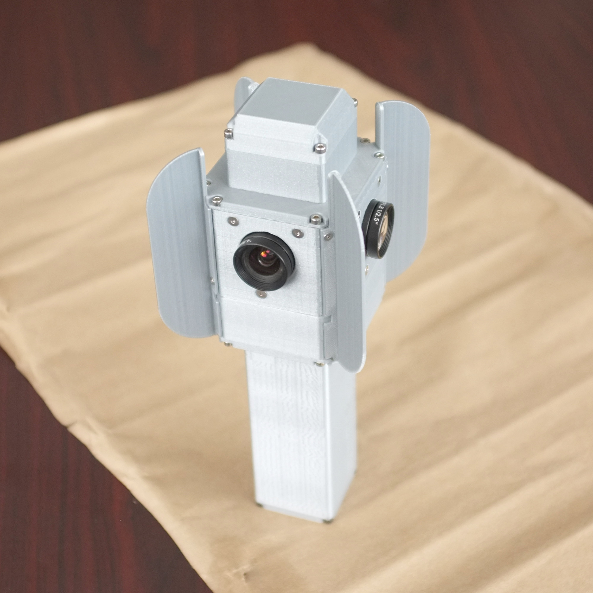
NC393 camera is fit for flight
The components for 10393 and other related circuit boards for the new NC393 camera series have been ordered and contract manufacturing (CM) is ready to assemble the first batch of camera boards.
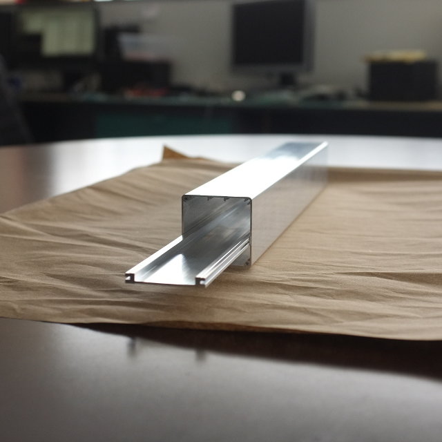
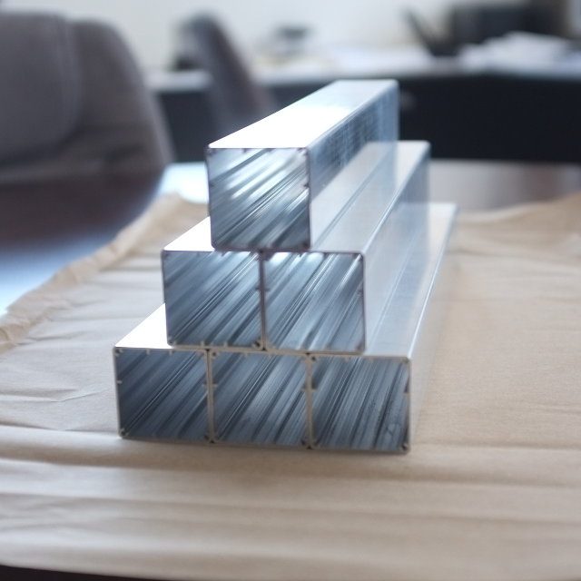
In the meantime, the extruded parts that will be made into NC393 camera body have been received at Elphel. The extrusion looks very slick with thin, 1mm walls made out of strong 6061-T6 aluminium, and weighs only 55g. The camera’s new lightweight design is suitable for use on a small aircraft. The heat frame responsible for cooling the powerful processor has also been extruded.
We are very pleased with the performance of Profile Precision Extrusions located in Phoenix, Arizona, which have delivered a very accurate product ahead of the proposed schedule. Now we can proudly engrave “Made in USA” on the camera, as now even the camera body parts are made in the United States.
Of course, we have tried to order the extrusion in China, but the intricately detailed profile is difficult to extrude and tolerances were hard to match, so when Profile Precision was recommended to us by local extrusion facilities we were happy to discover the outstanding quality this company offers.
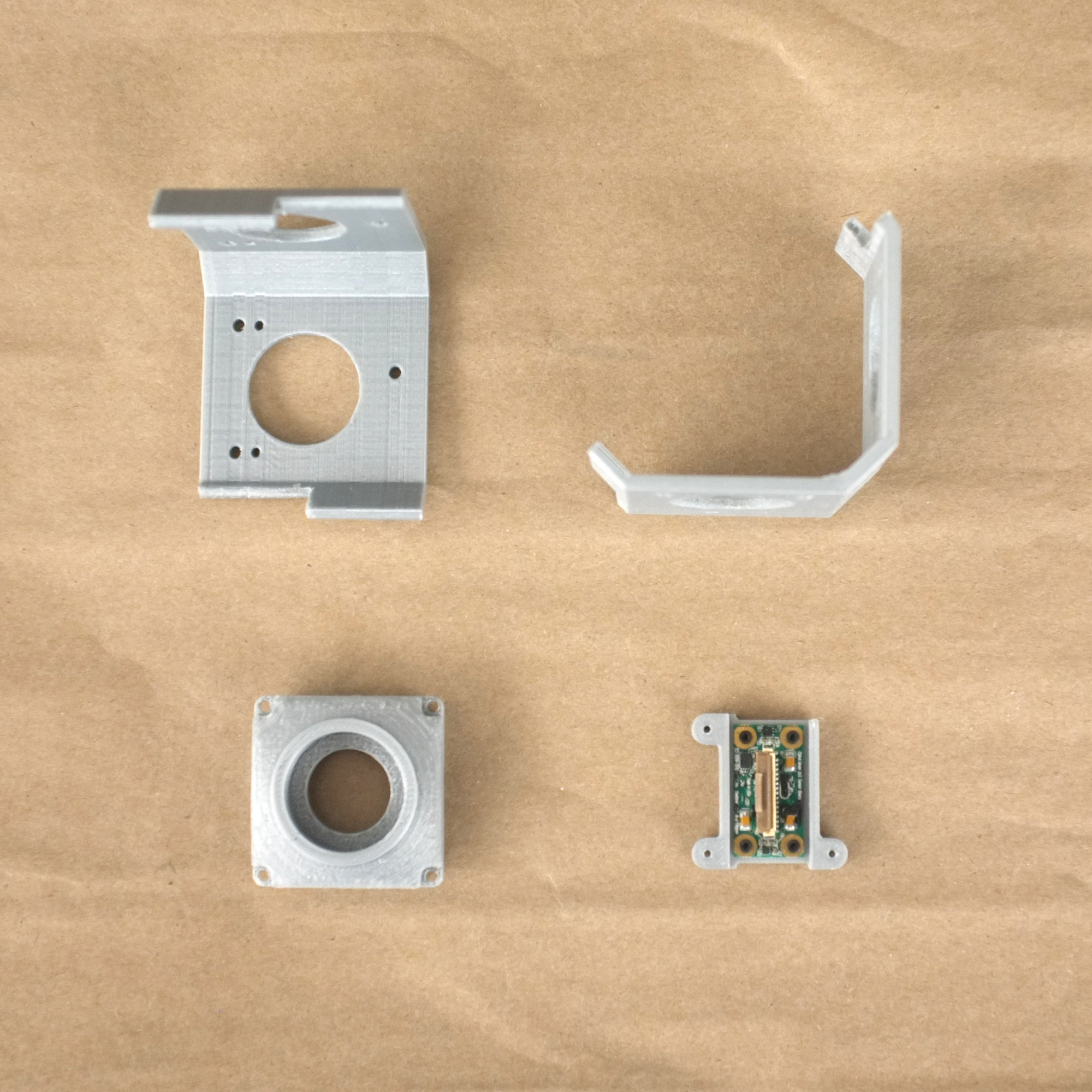
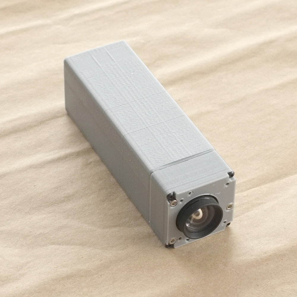
While waiting for the extruded parts we have been playing with another new toy: the 3D printer. We have been creating prototypes of various camera models of the NC393 series. The cameras are designed and modelled in a 3D virtual environment, and can viewed and even taken apart by mouse click thanks to X3dom technology. The next step is to build actual parts on the 3D printer and physically assemble the camera prototypes, which will allow us to start using the prototypes in the physical world: finding what features are missing, and correcting and finalizing the design. For example, when the mini-panoramic NC393-4PI4 camera prototype was assembled it was clear that it needs the 4 fins (now seen on the final model) to protect the lenses from touching the surfaces as well as to provide shade from the sun. NC393-4PI4 and NC393-4PI4-IMU-GPS are small 360 degree panoramic cameras assembled with 4 fish-eye lenses especially suitable for interior panoramic applications.
The prototypes are not as slick as the actual aluminium bodies, but they give a very good example of what the actual cameras will look like.
As of today, the 10393 and other boards are in production, the prototypes are being built and tested for design functionality, and the aluminium extrusions have been received. With all this taken care of, we are now less than one month away from the NC393 being offered for sale; the first cameras will be distributed to the loyal Elphel customers who have placed and pre-paid orders several weeks ago.
Elphel 353 series quick start guide
Command line access:
← Older revision Revision as of 20:13, 11 February 2016 Line 117: Line 117: ==Command line access== ==Command line access== -a) '''SSH'''+a) '''SSH''' (outdated, drops connections, please, use Telnet) In the terminal window: ssh root@192.168.0.9 In the terminal window: ssh root@192.168.0.9 OlegRequest for quote 393-1
Created page with "Elphel, Inc. invites the machine shops to Quote manufacturing of the following parts: {| class="wikitable" style="background:#fcfcfc; " border="1" |+ Metal Parts |- ! Part !! Q..."
New page
Elphel, Inc. invites the machine shops to Quote manufacturing of the following parts:{| class="wikitable" style="background:#fcfcfc; " border="1"
|+ Metal Parts
|-
! Part !! QTY per Unit !! Notes
|-
| [[Elphel_camera_parts_0393-12#0393-12-29_-_Sensor_front_end.2C_CS-mount|0393-12-29 - Sensor front end, CS-mount ]] || 10 || 100 ||
|-
| [[Elphel_camera_parts_0393-12#0393-12-30_-_Sensor_adjustment_plate|0393-12-30 - Sensor adjustment plate ]] || 10 || 100 ||
|-
| [[Elphel_camera_parts_0393-11#0393-11-04_-_Cooling_fan_enclosure|0393-11-04 - Cooling fan enclosure ]] || 10 || 100 ||
|-
| [[Elphel_camera_parts_0393-11#0393-11-10_-_CPU_heat_plate|0393-11-10 - CPU heat plate]] || 10 || 100 ||
|-
| [[Elphel_camera_parts_0393-18#0353-18-30_-_tripod_mount_nut.2C_1.2F4-20_thread|0353-18-30 - tripod mount nut, 1/4-20 thread ]] || 10 || 100 ||
|-
| [[Elphel_camera_parts_0393-18#0353-18-31_-_tripod_mount_plate|0353-18-31 - tripod mount plate ]] || 10 || 100||
|-
|}
Please, read the [[Supplier_Terms_and_Conditions|Suppliers Terms and Conditions]] and send the Proposals by e-mail: [mailto://supplies@elphel.com supplies@elphel.com] Olga
Poky 2.0 manual
Setup:
← Older revision Revision as of 23:25, 1 February 2016 Line 40: Line 40: git clone -b master https://github.com/Elphel/meta-elphel393.git meta-elphel393 git clone -b master https://github.com/Elphel/meta-elphel393.git meta-elphel393 - cd meta-elphel393; git checkout 9013e39faac2f99c8dda36244ae8a111c72214e1; cd ..+ cd meta-elphel393; git checkout 2bf73c48be5433002144bc9126bdc9c44b30b98c; cd .. git clone -b master https://github.com/Xilinx/meta-xilinx.git meta-xilinx git clone -b master https://github.com/Xilinx/meta-xilinx.git meta-xilinx OlegEyesis4Pi
← Older revision
Revision as of 22:30, 1 February 2016
Line 1:
Line 1:
-<!--<span style='color:red;font-size:25px;font-weight:bold'>50% off on the current Eyesis4Pi camera model!</span>+<span style='color:red;font-size:25px;font-weight:bold'>50% off on the current Eyesis4Pi camera model!</span>
* <span style='font-size:20px'>Due to development of the new 10393 camera series all current models including Eyesis4Pi are offered at 50% discount while supply lasts</span> * <span style='font-size:20px'>Due to development of the new 10393 camera series all current models including Eyesis4Pi are offered at 50% discount while supply lasts</span>
* <span style='font-size:20px'>Upgrade to 10393 will be available for the current Eyesis4Pi cameras</span> * <span style='font-size:20px'>Upgrade to 10393 will be available for the current Eyesis4Pi cameras</span>
--->
== [[Image:hp_banner_eyesis.png]]<br> == == [[Image:hp_banner_eyesis.png]]<br> ==
Oleg
Price list
← Older revision
Revision as of 22:29, 1 February 2016
Line 1:
Line 1:
-<!--<span style='color:red;font-size:25px;font-weight:bold'>50% off on the current Eyesis4Pi camera model!</span>+<span style='color:red;font-size:25px;font-weight:bold'>50% off on the current Eyesis4Pi camera model!</span>
* <span style='font-size:20px'>Due to development of the new 10393 camera series all current models including Eyesis4Pi are offered at 50% discount while supply lasts</span> * <span style='font-size:20px'>Due to development of the new 10393 camera series all current models including Eyesis4Pi are offered at 50% discount while supply lasts</span>
* <span style='font-size:20px'>Upgrade to 10393 will be available for the current Eyesis4Pi cameras</span> * <span style='font-size:20px'>Upgrade to 10393 will be available for the current Eyesis4Pi cameras</span>
--->+
= Ordering = = Ordering =
Oleg
Poky 2.0 manual
Setup:
← Older revision Revision as of 01:53, 1 February 2016 Line 46: Line 46: git clone -b master git://git.openembedded.org/meta-openembedded meta-openembedded git clone -b master git://git.openembedded.org/meta-openembedded meta-openembedded - cd meta-openembedded; git checkout 3d2c0f5902cacf9d8544bf263b51ef0dd1a7218c; cd ..+ cd meta-openembedded; git checkout 73854a05565b30a5ca146ac53959c679b27815aa; cd .. '''#Part 2 : init environment and auto-fill Yocto's conf-files''' '''#Part 2 : init environment and auto-fill Yocto's conf-files''' Oleg