10369
From ElphelWiki
Revision as of 12:04, 9 November 2011 by Oleg (talk | contribs) (→J15 - SYNC (external))
Contents
- 1 10369
- 1.1 Features
- 1.2 Adapters
- 1.3 Notes
- 1.4 On-board I2C devices
- 1.5 Connectors
- 1.5.1 J1 - AUX (from the CPU board)
- 1.5.2 J2 - IDE (from the CPU board)
- 1.5.3 J3 - Power (from the CPU board)
- 1.5.4 J4 - Power (optional - to the next boards)
- 1.5.5 J5 - Power (optional 3.3V in)
- 1.5.6 J6 - IDE (to adapter/riser)
- 1.5.7 J7 - SATA
- 1.5.8 J8 - USB0 (to external)
- 1.5.9 J9 - USB1 (to internal)
- 1.5.10 J10 - USB2 (to internal)
- 1.5.11 J11 - USB3 (to internal)
- 1.5.12 J12 - SYNC (internal, master)
- 1.5.13 J13 - SYNC (internal, slave)
- 1.5.14 J14 - SYNC (internal, slave)
- 1.5.15 J15 - SYNC (external)
- 1.5.16 J16 - RS-232
- 1.5.17 J17 - Fan
- 1.5.18 W2-W4 - Terminals for external temperature sensor
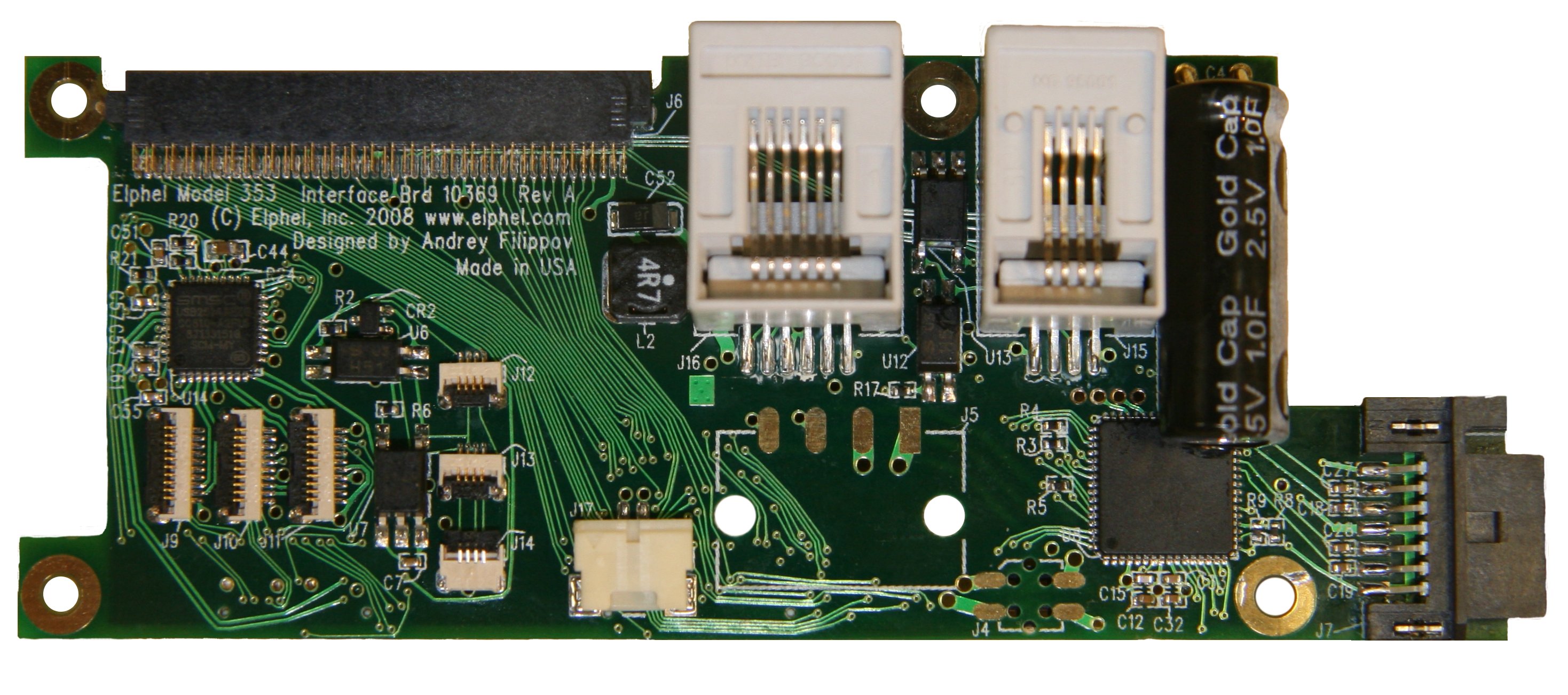
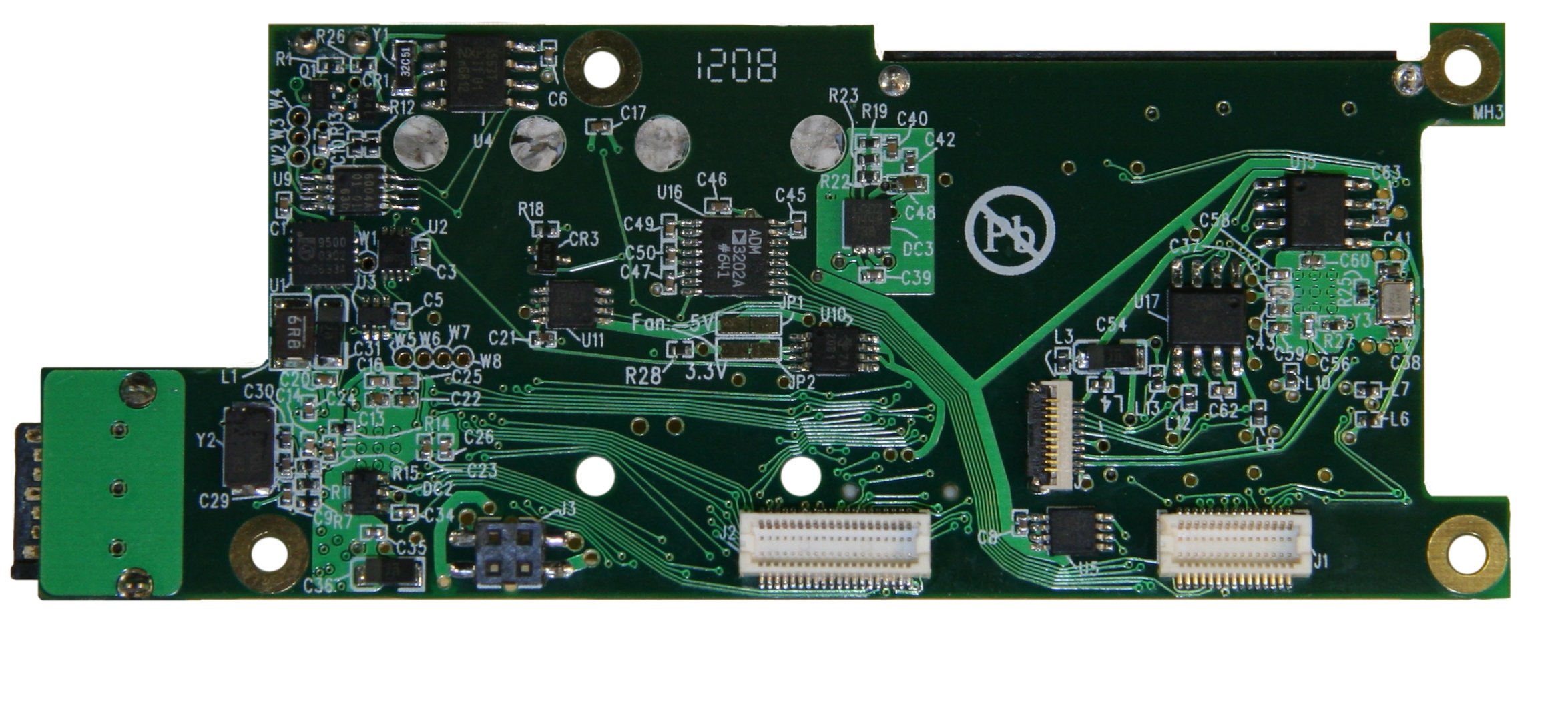
10369


Features
10369 interface board is an extension board for the Elphel 353/363 series cameras.
- It provides multiple interfaces and peripherals to the camera:
- SATA port for external disk drives
- Compact Flash (in "True IDE" mode) and IDE HDD ports (with adapter/riser boards: 103691, 103692)
- RS-232 port
- Opto-isolated I/O port for synchronizing the camera or synchronizing together multiple cameras (modular RJ14 external connector)
- Opto-isolated I/O port for synchronizing multiple camera modules in the same enclosure (flex cable connectors)
- Digital thermometer with internal ("system") and external thermal sensor (emitter-base junction of PNP or NPN transistor)
- Fan driver, controlled by the digital thermometer with programmable on/off temperature
- Clock/calendar with the super-capacitor backup power
- EEPROM for the board identification and configuration
Adapters
10369 board is used with several adapters:
- 103691 - adapter/riser to connect one or two Compact Flash cards
- 103692 - adapter for the ZIF-type (flex cable connector) 1.8" HDD
- 103693 - USB type A (host) connector adapter mounted on the back panel of the Elphel Model 353 camera.
- 103695 - IMU adapter board.
- 103696 - Serial GPS with synchronization signal adapter board.
- RJ45/DB9F_Modular_Adapter - DB9F to RJ45/RJ25 modular adapter
Notes
- It can be impossible to mount an external SATA disk to the camera with an internal 18"HDD (NC353L-369A-HDD) as the internal disk (Toshiba MK1214GAH) does not react on master/slave-option bus and also it doesn't tristate the signals it shares with the SATA bridge.
On-board I2C devices
8-bit port/EEPROM
This combined port/EEPROM chip for the board identification and it also controls some IDE-related parameters of the board.
- Manufacturer - NXP Semiconductors
- Datasheet - PCA9500_3.pdf
- I2C slave addresses:
- 8-bit port: 0x40
- EEPROM: 0xa0
8-bit port
The 8-bit port is bidirectional with weak pull up (strong pull up during write pulse), so to work as input bit has to be programmed with "1". There is a single "register" that corresponds to I/O bits that does not have any address, so a raw mode is used during I2C read/write. Default value after power up is 0xff (all bits "1").
Note: rebooting the camera does not reset the port - values are preserved.
| bit | Direction | Signal | Notes |
|---|---|---|---|
| 0 | INPUT | CF0PRESENT | pulled to "0" by the CF0 (bottom, master) card if it is installed (otherwise returns "1") |
| 1 | INPUT | CF1PRESENT | pulled to "0" by the CF1 (top, slave) card if it is installed (otherwise returns "1") |
| 2 | OUTPUT | EN_CFM | enable CF0 (master). If set to "0" the CF0 card is reset (gives way to SATA) |
| 3 | OUTPUT | EN_CFS | enable CF1 (slave). If set to "0" the CF1 card is reset (gives way to SATA) |
| 4 | OUTPUT | EN_SATA | enable SATA port. If set to "0" the SATA port is reset (gives way to CF) |
| 5 | OUTPUT | SATA_MASTER | if set to "0" SATA will be slave IDE device, with "1" (default) it is IDE master |
| 6 | OUTPUT | DIS_SPREAD | disable spread spectrum in SATA (default). If set to "0" the SATA uses spread spectrum |
| 7 | BIDIR | GPIO7 | reserved, connected to W1 solder point |
Example - reading status of CF cards installed):
http://192.168.0.9/i2c.php?bus=1&raw=0x2000
result (CF0 present, CF1 - not installed, outputs - default):
<?xml version="1.0"?>
<i2c>
 <width>8</width>
 <bus>1</bus>
 <slave>0x40</slave>
 <data>254</data>
 <rdata>254</rdata>
 <hex_data>0xfe</hex_data>
</i2c>
Example - setting SATA to be IDE slave (needed if bottom CF card or internal HDD is installed):
http://192.168.0.9/i2c.php?bus=1&raw=0x2000&data=0xdf
then reboot (not power cycle) the camera - the SATA disk will be IDE slave, CF0 - IDE master
Identification EEPROM
Example - reading EEPROM data (it stores up to 256 bytes, containing text xml data):
http://192.168.0.9/i2c.php?cmd=fromEEPROM
Result:
<?xml version="1.0" standalone="yes"?>
<board>
 <brand>Elphel</brand>
 <model>10369</model>
 <rev>A</rev>
 <serial>000101</serial>
 <time>1214875806</time>
</board>
Remote/local digital temperature sensor
The 10369 board's built-in temperature sensor measures on-chip ("system") temperature. It can also be configured to measure the temperature of an additional sensor (any general purpose small transistor) soldered to the pads W2-W3, as detailed below in the 'Connectors' section. The same circuit can also be used to automatically control a 3.3V or 5.0V fan (connected to J17), based on the output of either the internal or optional external temperature sensor. To configure the fan controller to run off the internal temperature sensor, terminals W2 and W3 should be soldered together.
- Manufacturer - NXP Semiconductors
- Datasheet - SA56004X_5.pdf
- I2C slave address: 0x90
Example - reading register 00 (LTHB : Local Temperature High Byte):
http://192.168.0.9/i2c.php?width=8&bus=1&adr=0x4800 // Reads register 00 (LTHB : Local Temperature High Byte)
Change the register to be read by adding the register number to the base address of 0x4800
http://192.168.0.9/i2c.php?width=8&bus=1&adr=0x4801 // Reads register 01 (RTHB : Remote Temperature High Byte)
This will return an XML file that includes the temperature register (signed char, °C), +48°C as in the example below:
<?xml version="1.0"?>
<i2c>
 <width>8</width>
 <bus>1</bus>
 <slave>0x90</slave>
 <adr>18432</adr>
 <hex_adr>0x4800</hex_adr>
 <data>48</data>
 <rdata>48</rdata>
 <hex_data>0x30</hex_data>
</i2c>
Clock/calendar
10369 has on-board clock/calendar with the backup power provided by the supercapacitor (1.0F x 2.5V) - it should enable clock to run for several weeks if the camera is left without power.
- Manufacturer - NXP Semiconductors
- Datasheet - PCF8563_6.pdf
- I2C slave address: 0xa2
Example - reading register 2 (seconds):
http://192.168.0.9/i2c.php?width=8&bus=1&adr=0x5102 // Add register number to the base address of 0x5100
Returns xml file that includes seconds portion of the current time - 54sec in the example below:
<?xml version="1.0"?>
<i2c>
 <width>8</width>
 <bus>1</bus>
 <slave>0xa2</slave>
 <adr>20738</adr>
 <hex_adr>0x5102</hex_adr>
 <data>54</data>
 <rdata>54</rdata>
 <hex_data>0x36</hex_data>
</i2c>
Example - setting camera system time to the CMOS clock/calendar time:
http://192.168.0.9/i2c.php?cmd=fromCMOS
If the clock calendar contains valid date/time, it returns xml file like following:
<i2c>
<result>
 "System clock is set to Tue Jul  1 01:01:53 UTC 2008"
</result>
</i2c>
Otherwise (time is not set or the capacitor ran out of charge):
<i2c>
<result>
 "Set system time error (probably CMOS clock is not set)"
</result>
</i2c>
In that case the clock/calendar should be set.
Example - read CMOS clock/calendar time:
http://192.168.0.9/i2c.php?cmd=readCMOS
Work in the same way as "fromCMOS" but without modification of camera system time.
Example - setting the clock/calendar
First - set the system clock (i.e. open camera web interface, it will set the camera system time to that of the computer), then open
http://192.168.0.9/i2c.php?cmd=toCMOS
The result should be just:
<i2c>
<result>OK</result>
</i2c>
Connectors
J1 - AUX (from the CPU board)
| Pin | Signal | Notes | Pin | Signal | Notes | |
|---|---|---|---|---|---|---|
| 1 | GND | 2 | GND | |||
| 3 | EXT[0] | GPIO | 4 | EXT[2] | GPIO | |
| 5 | EXT[1] | GPIO | 6 | EXT[3] | GPIO | |
| 7 | GND | 8 | GND | |||
| 9 | EXT[4] | GPIO | 10 | EXT[6] | GPIO | |
| 11 | EXT[5] | GPIO | 12 | EXT[7] | GPIO | |
| 13 | GND | 14 | GND | |||
| 15 | EXT[8] | GPIO | 16 | EXT[10] | GPIO | |
| 17 | EXT[9] | GPIO | 18 | EXT[11] | GPIO | |
| 19 | GND | 20 | GND | |||
| 21 | CTS | RS232 | 22 | RTS | RS232 | |
| 23 | RXD | RS232 | 24 | TXD | RS232 | |
| 25 | VP33 | +3.3V | 26 | VP33 | +3.3V | |
| 27 | U0VM | USB | 28 | U0VP | USB | |
| 29 | VP33 | +3.3V | 30 | VP33 | +3.3V |
J2 - IDE (from the CPU board)
| Pin | Signal | Notes | Pin | Signal | Notes | |
|---|---|---|---|---|---|---|
| 1 | IDE_RST | 2 | GND | |||
| 3 | IDE_D[7] | 4 | IDE_D[8] | |||
| 5 | IDE_D[6] | 6 | IDE_D[9] | |||
| 7 | IDE_D[5] | 8 | IDE_D[10] | |||
| 9 | IDE_D[4] | 10 | IDE_D[11] | |||
| 11 | IDE_D[3] | 12 | IDE_D[12] | |||
| 13 | IDE_D[2] | 14 | IDE_D[13] | |||
| 15 | IDE_D[1] | 16 | IDE_D[14] | |||
| 17 | IDE_D[0] | 18 | IDE_D[15] | |||
| 19 | GND | 20 | GND | |||
| 21 | IDE_DMARQ | 22 | GND | |||
| 23 | IDE_IOW | 24 | GND | |||
| 25 | IDE_IOR | 26 | GND | |||
| 27 | IDE_IORDY | 28 | GND | |||
| 29 | IDE_DMACK | 30 | GND | |||
| 31 | IDE_INTRQ | 32 | EXT_OE | not used | ||
| 33 | IDE_A[1] | 34 | -- | |||
| 35 | IDE_A[0] | 36 | IDE_A[2] | |||
| 37 | IDE_CS0 | 38 | IDE_CS1 | |||
| 39 | -- | 40 | GND |
J3 - Power (from the CPU board)
| Pin | Signal | Notes | Pin | Signal | Notes | |
|---|---|---|---|---|---|---|
| 1 | GND | 3 | VP33 | +3.3V | ||
| 2 | LPWR48M | -48V, isolated, primary | 4 | LPWR48P | +48V, isolated, primary |
Note: +/- 48V are non-regulated input power rails. For 12V or 24V camera modifications these lines will also have +/-12V or +/-24V.
J4 - Power (optional - to the next boards)
| Pin | Signal | Notes | Pin | Signal | Notes | |
|---|---|---|---|---|---|---|
| 1 | GND | 3 | VP33 | +3.3V | ||
| 2 | LPWR48M | -48V, isolated, primary | 4 | LPWR48P | +48V, isolated, primary |
Note: J4 is normally not installed. It is used in some camera modificatios where ther is another board on top of the 10369 that needs power - J4 is located oppposite to J3, same as on 10353 system board.
J5 - Power (optional 3.3V in)
| Pin | Signal | Notes |
|---|---|---|
| 1 | GND | |
| 2 | VP33 | +3.3V |
| 3 | LPWR48M | -48V, isolated, primary |
| 4 | LPWR48P | +48V, isolated, primary |
Note: J5 is normally not installed. It may be used in multi-camera systems to provide 3.3V from the commomn to all camera modules power supply (DC-DC converter on 10353 should not be installed).
J6 - IDE (to adapter/riser)
| Pin | Signal | Notes | Pin | Signal | Notes | |
|---|---|---|---|---|---|---|
| 1 | CF1PRESENT | GND if CF1 installed | 2 | GND | ||
| 3 | IDE_D[11] | 4 | IDE_D[3] | |||
| 5 | IDE_D[12] | 6 | IDE_D[4] | |||
| 7 | IDE_D[13] | 8 | IDE_D[5] | |||
| 9 | IDE_D[14] | 10 | IDE_D[6] | |||
| 11 | IDE_D[15] | 12 | IDE_D[7] | |||
| 13 | IDE_CS1 | 14 | IDE_CS0 | |||
| 15 | -- | 16 | -- | |||
| 17 | IDE_IOR | 18 | GND | |||
| 19 | IDE_IOW | 20 | -- | |||
| 21 | -- | 22 | -- | |||
| 23 | IDE_INTRQ | 24 | -- | |||
| 25 | +3.3V | 26 | +3.3V | |||
| 27 | GND | 28 | EXT[0](SCL) | |||
| 29 | RST_CFS | Reset master | 30 | EXT[0](SDA) | ||
| 31 | RST_CFM | Reset slave | 32 | -- | ||
| 33 | IDE_IORDY | 34 | GND | |||
| 35 | IDE_DMARQ | 36 | IDE_A[2] | |||
| 37 | IDE_DMACK | 38 | IDE_A[1] | |||
| 39 | IDE_DASP | 40 | IDE_A[0] | |||
| 41 | IDE_PDIAG | 42 | IDE_D[0] | |||
| 43 | IDE_D[8] | 44 | IDE_D[1] | |||
| 45 | IDE_D[9] | 46 | IDE_D[2] | |||
| 47 | IDE_D[10] | 48 | -- | |||
| 49 | GND | 50 | CF0PRESENT | GND if CF0 installed |
J7 - SATA
| Pin | Signal | Notes |
|---|---|---|
| 1 | GND | |
| 2 | SATATP | Transmit + |
| 3 | SATATM | Transmit - |
| 4 | GND | |
| 5 | SATARM | Receive - |
| 6 | SATARP | Receive + |
| 7 | GND |
J8 - USB0 (to external)
| Pin | Signal | Notes |
|---|---|---|
| 1 | GND | System ground, needs series inductor (on 103693) |
| 2 | DP1 | USB data + |
| 3 | DM1 | USB data - |
| 4 | PW1 | USB +5V power (switched) |
| 5 | GND | |
| 6 | EXT[0] | i2c SCL |
| 7 | EXT[1] | i2c SDA |
| 8 | EXT[6] | GPIO |
| 9 | EXT[7] | GPIO |
| 10 | P3_1 | +3.3V power |
J9 - USB1 (to internal)
| Pin | Signal | Notes |
|---|---|---|
| 1 | GND | |
| 2 | DP2 | USB data + |
| 3 | DM2 | USB data - |
| 4 | PW2 | USB +5V power (switched) |
| 5 | GND | |
| 6 | EXT[0] | i2c SCL |
| 7 | EXT[1] | i2c SDA |
| 8 | EXT[2] | GPIO |
| 9 | EXT[3] | GPIO |
| 10 | P3_2 | +3.3V power |
J10 - USB2 (to internal)
| Pin | Signal | Notes |
|---|---|---|
| 1 | GND | |
| 2 | DP3 | USB data + |
| 3 | DM3 | USB data - |
| 4 | PW3 | USB +5V power (switched) |
| 5 | GND | |
| 6 | EXT[0] | i2c SCL |
| 7 | EXT[1] | i2c SDA |
| 8 | EXT[4] | GPIO |
| 9 | EXT[5] | GPIO |
| 10 | P3_3 | +3.3V power |
J11 - USB3 (to internal)
| Pin | Signal | Notes |
|---|---|---|
| 1 | GND | |
| 2 | DP4 | USB data + |
| 3 | DM5 | USB data - |
| 4 | PW4 | USB +5V power (switched) |
| 5 | GND | |
| 6 | EXT[0] | i2c SCL |
| 7 | EXT[1] | i2c SDA |
| 8 | EXT[6] | GPIO |
| 9 | EXT[7] | GPIO |
| 10 | P3_4 | +3.3V power |
J12 - SYNC (internal, master)
| Pin | Signal | Notes |
|---|---|---|
| 1 | GND | Driver return |
| 2 | ISYNCDR | Driver output |
| 3 | ISYNC1 | Optoisolated I/O |
| 4 | ISYNC2 | Optoisolated I/O return |
Note: Connect J12 to J14 on the next camera in chain with a 4-conductor flex jumper, then from J13 of that next camera to the next in chain's J14, and so on. J12 and J13 have contacts on the bottom side, J14 - on the top to simplify chaining.
J13 - SYNC (internal, slave)
| Pin | Signal | Notes |
|---|---|---|
| 1 | ISYNC2 | Optoisolated I/O return |
| 2 | ISYNC1 | Optoisolated I/O |
| 3 | ISYNC1 | Optoisolated I/O |
| 4 | ISYNC2 | Optoisolated I/O return |
Note: Connect J12 to J14 of the next camera module in chain.
J14 - SYNC (internal, slave)
| Pin | Signal | Notes |
|---|---|---|
| 1 | ISYNC2 | Optoisolated I/O return |
| 2 | ISYNC1 | Optoisolated I/O |
| 3 | ISYNC1 | Optoisolated I/O |
| 4 | ISYNC2 | Optoisolated I/O return |
Note: Connect J14 to J13 of the previous camera module in chain (if the previous is not the master). If it is the master, connect J14 to the master's J12 instead of the J13
J15 - SYNC (external)
| Pin | Signal | Notes |
|---|---|---|
| 1 | GND | Driver return |
| 2 | XSYNC1 | Optoisolated I/O |
| 3 | XISYNC2 | Optoisolated I/O return |
| 4 | XSYNCDR | Driver output |
Note: In order to synchronize multiple cameras connect the pins 2 on all cameras together, same for all the pins 3. Additionally connect pin 1 on the 'master' (synchronization source) camera to pin 3, pin 4 - with pin2.

J16 - RS-232
| Pin | Signal | Notes |
|---|---|---|
| 1 | XCTS | CTS |
| 2 | XRXD | RxD |
| 3 | GND | |
| 4 | GND | |
| 5 | XTXD | TxD |
| 6 | XRTS | RTS |
Default speed: 115200
J17 - Fan
| Pin | Signal | Notes |
|---|---|---|
| 1 | FANPOS | Fan positive terminal (Red) |
| 2 | GND | Fan negative terminal (Black) |
Note: Default configuration supports 3.3VDC fans, in order to switch to 5.0V you need to open (cut trace) jumper JP2 and close (solder together terminals of) jumper JP1.
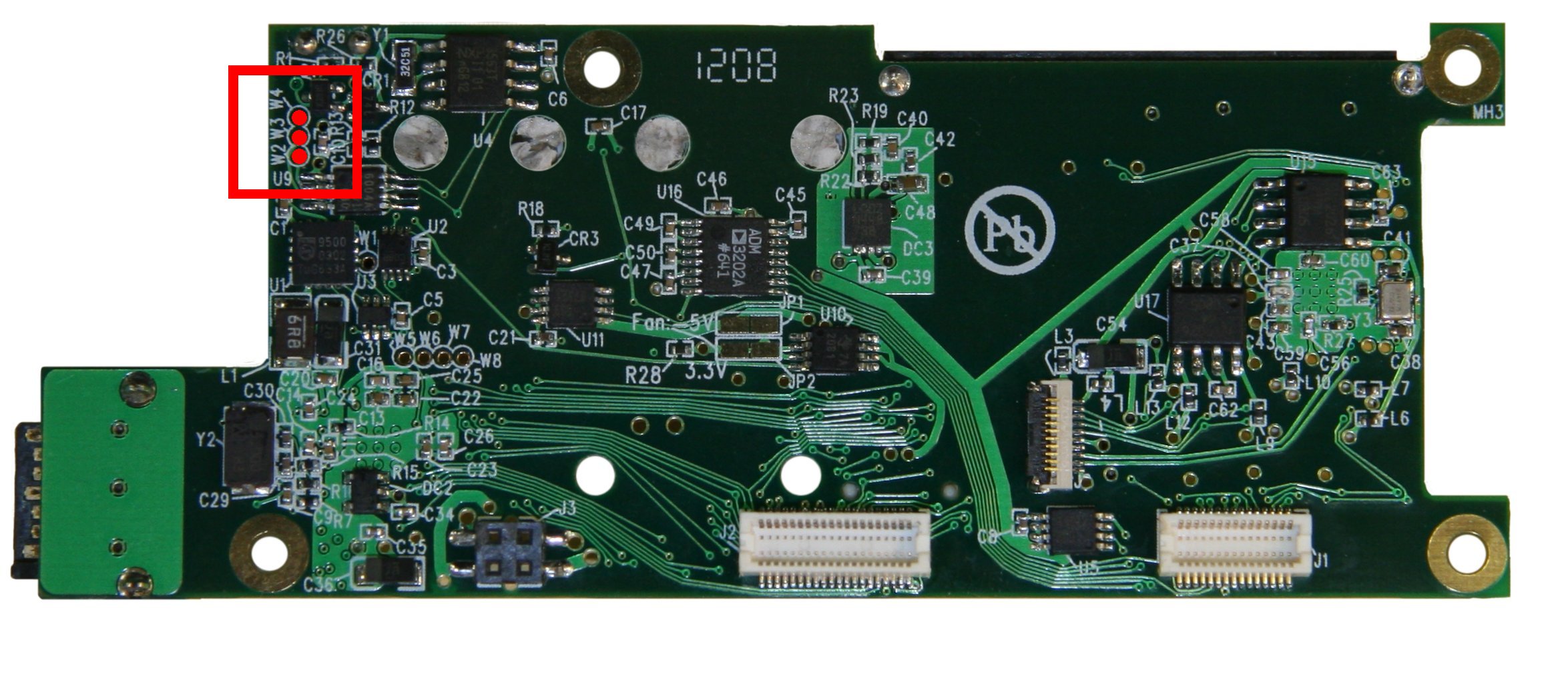
W2-W4 - Terminals for external temperature sensor


| Pin | Signal | Notes |
|---|---|---|
| W2 | TSNSP | Thermal sensor positive |
| W3 | TSNSP | Thermal sensor negative |
| W4 | GND | connect to sensor cable shield |
Note: To make a simple temperature sensor for this circuit, a small NPN or PNP transistor can be used. It is best to use a shielded, twisted pair cable to connect the external sensor to the terminals on the 10369 board. Start by soldering the shield wire to GND on W4. Then solder together the base and the collector of the sensor transistor. If using an NPN transistor (i.e. 2N3904), solder one wire from the transistor's base to W2, and the other wire from the emitter to W3. If using a PNP transistor (i.e. 2N3906), solder one wire from the transistor's emitter to W2, and the other wire from the base to W3. If no external sensor is used, but a temperature controlled cooling fan is needed, W2 and W3 should be connected together. This will allow the 10369 board's built in fan control to set the fan speed based on the board's internal temperature sensor.